by Joseph D. Mazzola, D.D.S
Case Overview
An 81-year-old female reported to my office to discuss the recent loss of a fixed partial denture that replaced tooth #14. The abutment teeth, #13 and #15, had also been removed. During the extraction of tooth #13, a root tip had been left behind due to its close proximity to the maxillary sinus.
The patient, who presented with no significant medical problems, requested a fixed partial denture as her restoration of choice using endosseous implants. The treatment was planned with study models to examine her occlusal scheme, along with intra- and extraoral photos and a CBCT scan.
Treatment Plan
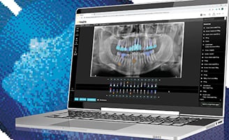
Pre-op CBCT
A surgical guide was created from a diagnostic wax-up of the final restoration to guide the path of the osteotomy. Next, the remaining root tip of tooth #13 was removed. A 13 x 3.5 mm Zimmer endosseous implant was placed in tooth position #13. Then, an osseous graft was performed.
A 10 x 5.7 mm Zimmer endosseous implant was then placed in tooth position #15 with a concurrent sinus lift. The ridge was idealized by removing and harvesting the exostosis evident on the buccal ridge of implant in tooth position #13. Following this, the verticle sinus lift was grafted into the sinus on the implant in tooth position #15. Facial grafting was performed as necessary on the implant in tooth position #13 using mineralized corto-cancellous allograph mixed with an autograft harvested from the patient.
CBCT Virtual Treatment Planning with Implants
After a five month healing period, the implants were exposed and tissue healing caps with the proper flair for the final abutments and a bridge were placed. After three weeks of healing, the restorative procedures commenced with the aid of the Carestream Dental CS 3500 intraoral scanner.
Restorative Procedure Using an Intraoral Scanner
I began planning the restoration by capturing a digital impression of the area of interest. To do this, I opened the CS 3500 acquisition software and selected the custom abutment. The software immediately launched into capture mode to begin scanning.
The sequence of virtual modeling started with the scan of the fixture head and soft tissue collar immediately after the tissue healing collar was removed, and continued until the entire quadrant was captured. This process guaranteed the accuracy of the soft tissue contour for the custom abutment fabrication. Once the soft tissue collar, implant head and the adjacent quadrant were captured, the opposing quadrant and bite were completed to create a virtual model of both quadrants in occlusion.
Upon completing the virtual modeling of both arches and the bite, we created a scan body virtual model to identify the position and angle of the implant located in the bone and the overlying tissue in three axis. We then exported this data to the lab, where the digital laboratory technician imported it into design software to virtually place the implant in the model and fabricate the final custom abutment and bridge.
Virtual Impression Copings: Scan Bodies
Scan bodies are similar to traditional indirect impression copings and are supplied by the implant company or the digital laboratory that will create the final abutment and crown.
Available as both indexed or non-indexed, scan bodies are placed on each fixture for scanning. Indexed scan bodies are preferred in cases using a cemented restoration with a custom abutment and crown or cemented bridges, while non-indexed scan bodies are used to create a screw retained one piece, abutment/crown restoration with minimum verticle clearance and angulation differences with multiple implants that are to be used in a splinted restorations. In this case, we used a scan body from our digital lab for a Zimmer Implant.
Submission of the Virtual Models to the Laboratory
We accessed the STL virtual models—which can be shared openly with any lab—through the Carestream Dental CS Imaging software. After uploading to a secure web portal, the virtual models were then sent electronically to our preferred digital laboratory.
To facilitate communication with the lab, I included a Word document prescription and requested that the lab email 2D screen shots of the abutments and final bridge for approval before milling.
Once we approved the images, the laboratory fabricated the patient’s final abutments and three unit bridge restoration. Going through the restoration process digitally ensured that the restoration could be seated in half the time it typically takes for conventional restorations.
Testimonial
In the last 12 years, I have focused my practice on using new digital technologies, such as CBCT, digital X-rays, practice management software, CAD/CAM dental restorations and especially virtual modeling with the innovative CS 3500 intraoral scanner.
The CS 3500 is an indispensable part of my practice now. It has an extremely user-friendly interface that can seamlessly integrate with all practice management software. The scanner fits well in anyone’s hand; it is lightweight and easy to manipulate. It’s “plug and play” capability (there’s no cumbersome
trolley) makes it easy to carry from operatory to operatory. The scanner comes with two heated, interchangeable scanner tips to make capturing images of either arch as easy as using your mouth mirror.
The CS Acquisition software has an intuitive workflow for image capture and creates unmatched virtual models with extreme accuracy. Plus, it has an open image file system, called STL files, that allows me to share virtual models with any of my favorite digital laboratories with no data transfer fees.
We use this innovative technology for full arch virtual models for orthodontic appliances, precision implant surgical guides, routine crown and bridge and implant custom abutments and final restorations.
To learn more, please visit us on the web at www.carestreamdental.com.
© 2024 Carestream Dental LLC. All Rights Reserved