by David Little, D.D.S.
Download PDF Version With Clinical Case Images
A healthy 77-year-old female patient (Fig. 1) presented in my office with the complaint that she could no longer wear her upper denture. In fact, she felt the denture had never truly fit properly. This had severely limited what she was able to eat and had affected her quality of life.
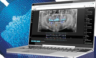
A comprehensive examination—clinical exam, digital panoramic, full-mouth radiographs and photographs—was performed. In keeping with my standard of care, a cone beam computed tomography (CBCT) scan with the CS 9000 3D extraoral imaging system was also taken. While the initial 2D images suggested enough bone present for implants (Fig. 2), a severely resorbed maxillary ridge was revealed by the cross sectional preoperative view of the CBCT scan (Fig. 3). Based on the CBCT findings, it was determined that bone grafting procedures would be necessary in order to make a screw-retained implant prosthesis possible.
Due to the resorbed maxillary ridge two grafting treatment options were put forward. The first option: an upper anterior and premolar bone graft using bone morphogenetic proteins (BMPs). The second option: autogenous bone grafts would be taken from the patient’s ramus, chin or hip. Either of these scenarios would be followed by the placement of six implants and a fixed restoration. Additionally, fewer implants could be placed and a removable overdenture could be used instead.
Treatment
The first option was selected by the patient, as she was seeking a fixed solution and was opposed to the autogenous graft procedures. The BMP rhBMP-2—which mimics a protein present in the body—was used for the bone graft. The patient’s existing denture was modified for use during the healing period—approximately four months—following the bone graft procedure. A post-graft CBCT scan was then taken to confirm the success of the graft and to plan the position of the implants (Fig. 4).
Next, planning software was used to predetermine where the six implants were to be placed (Fig. 5). After placing gingival sulcus formers (Fig. 6), the existing denture was modified and relined for use until the final prosthesis was ready. Then, abutments were positioned, after which the tissue was contoured with a soft tissue laser (Fig. 7). A verification jig was used to check the accuracy of the abutment level impression (Fig. 8). This was done to confirm that the bar would have a passive fit. A titainium bar was designed and milled using CAD/CAM technology (Fig. 9). To ensure approval, the bar was fitted with esthetic denture teeth, created in wax and tried-in (Fig. 10). Finally, the case was delivered (Fig. 11). The screws were torqued to 15 μm and teflon tape and composite were used to close the access holes.
The final outcome of the case resulted in the patient being able to securely wear her upper denture for the first time (Fig. 12). She was able to once again enjoy foods that had been off-limits due to her poorly fitting denture.
Testimonial
I’m a big proponent of seeing the end before you start and planning implants from the restoration backwards. With this case, just looking at the 2D pano it appeared as if we had enough bone. However, when we did the 3D scan with the CS 9000 3D, we immediately knew that there was not enough bone to do implants. Having that 3D technology and knowing exactly what we needed to be able to get the patient to where she wanted to go, that’s really what we uncovered. We were able to graft exactly where we needed to, take another CBCT scan, virtually plan the implants and give her the result that we wanted. Immediately, you could see her just light up. It was so rewarding.
© 2024 Carestream Dental LLC. All Rights Reserved